Profile Real-Time Preview
CIMTool 2.3.0 introduces the Profile Real-Time Preview feature, which renders a live UML class diagram of the active CIM profile directly within the CIMTool workbench. The diagram updates automatically each time the profile is saved, giving profile designers an immediate, visual representation of the profile's current state without leaving the application or switching to an external tool.
The Profile Real-Time Preview view is part of the default CIMTool workbench layout. In CIMTool, a perspective is a named arrangement of views, editors, and toolbars that is optimized for a particular type of work. The default CIMTool perspective is pre-configured for profile design and includes the Profile Real-Time Preview as one of its built-in views, visible as a tab in the lower portion of the workbench. No manual setup is required to use it.
Click on the image to present a larger view.
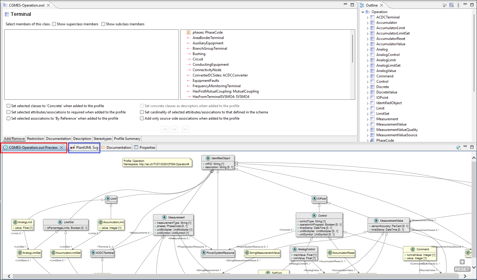
The Profile Real-Time Preview view tracks whichever profile is currently active in the profile editor and updates in place when focus moves to a different profile. The diagram is pan-and-zoom capable: holding Ctrl and scrolling zooms in or out; clicking and dragging pans the viewport. This is especially practical when working with large profiles whose full diagram extends well beyond the visible area of the view.
Note
The Profile Real-Time Preview view is distinct from the PlantUML Svg view that also appears in the default workbench layout (outlined in blue in the screenshot above). The PlantUML Svg view is a general-purpose PlantUML renderer that displays whatever .puml file is currently open or selected in the editor. The Profile Real-Time Preview, by contrast, is purpose-built for profile design work: it automatically tracks the active profile and regenerates its diagram on every save, with no manual file selection required.
Beyond visualizing the profile's structure, the Profile Real-Time Preview serves a second purpose that is especially valuable when building large or complex profiles: it surfaces incomplete or invalid profile definitions directly within the rendered diagram using distinct visual cues. This makes it possible to identify and correct structural problems as they arise, rather than discovering them only after a lengthy, systematic post-completion review.
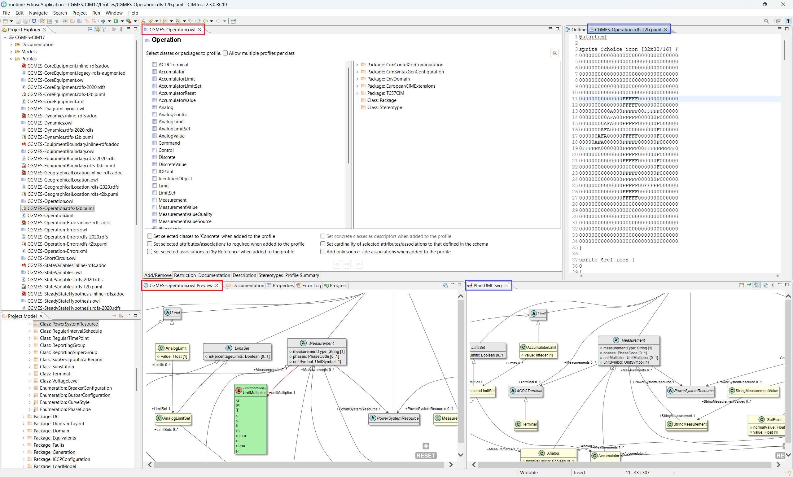
Because the two views serve different purposes, they can be used together. The PlantUML Svg view can be repositioned within the workbench by dragging its tab to a different panel, making it possible to display both views simultaneously side by side. The screenshot below illustrates this arrangement, and demonstrates the key difference between them: the Profile Real-Time Preview (left) renders definition errors using distinct visual cues, flagging issues within the profile definition. The PlantUML Svg view (right), rendering the same profile as a standard diagram, shows no such indicator even though the issue exists in the profile.
Click on the image to present a larger view.
Historically, validating a large profile required a meticulous inspection of every class, attribute, and association definition in the profile editor, a process that was time-consuming and error-prone precisely because definition problems had no visible presence in the workspace. The Profile Real-Time Preview eliminates that burden by making errors immediately visible each time the profile is saved.
Diagram Style and Target Schema Type
A CIM profile definition is shaped by its intended target artifact, the type of schema or serialization format the profile is ultimately meant to produce. The style of diagram rendered by the Profile Real-Time Preview reflects this: CIMTool generates a PlantUML diagram appropriate for the profile's target schema type, and it is within that diagram that any definition errors will be visualized.
When a new project is created, the diagram style defaults to puml-rdfs-t2b.
If the project is primarily targeting a different schema type (for example,
XSD), the default should be overridden by updating the project-level preference.
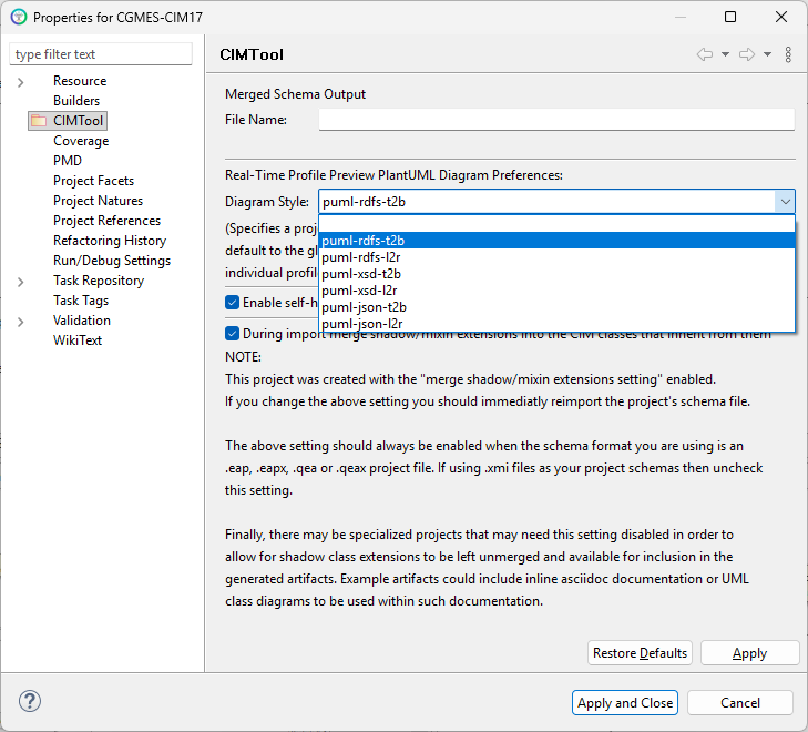
Right-click the project in the Project Explorer, select Properties,
navigate to CIMTool, and select the appropriate diagram style from the
Diagram Style dropdown. For an XSD-oriented project, for instance,
puml-xsd-t2b or puml-xsd-l2r would be the appropriate choice. Selecting
the correct diagram style ensures that the errors visualized in the Real-Time
Preview are relevant to the target schema type the profile is being designed for.
Under Real-Time Profile Preview PlantUML Diagram Preferences, the Diagram Style dropdown presents the available options:
Click on the image to present a larger view.
| Diagram Style | Target Schema Type | Layout |
|---|---|---|
puml-rdfs-t2b |
RDFS | Top-to-bottom |
puml-rdfs-l2r |
RDFS | Left-to-right |
puml-xsd-t2b |
XSD | Top-to-bottom |
puml-xsd-l2r |
XSD | Left-to-right |
puml-json-t2b |
JSON Schema | Top-to-bottom |
puml-json-l2r |
JSON Schema | Left-to-right |
This project-level setting applies as the default for all profiles in the project. It can be overridden on a per-profile basis from within the profile's own properties. The layout orientation, top-to-bottom or left-to-right, is a presentational preference and has no effect on the content of the diagram or the errors it surfaces.
The type of errors that can appear in the diagram depends on the target schema type selected. Some errors are common to all diagram styles; others are specific to the conventions and constraints of a particular target schema type. The sections below address each target schema type in turn, describing how errors are visualized within it and how to resolve each one.
Working with the Preview on a Second Monitor
The Profile Real-Time Preview view can be detached from the workbench entirely and moved to a separate window (for example, onto a second monitor) by dragging its tab away from its current panel and releasing it outside the workbench boundary. Once detached, the view can be maximized to fill the full screen, giving the diagram the maximum possible space while leaving the profile editor and the rest of the workbench fully accessible on the primary monitor. This arrangement is particularly effective when working with large profiles whose diagrams would otherwise require significant panning and zooming to navigate within a docked view.
Click on the image to present a larger view.
The next set of screenshots are used for illustration purposes and show a profile that contains a wide range of profile errors, each numbered 1 through 8 for reference.
Click on the image to present a larger view.
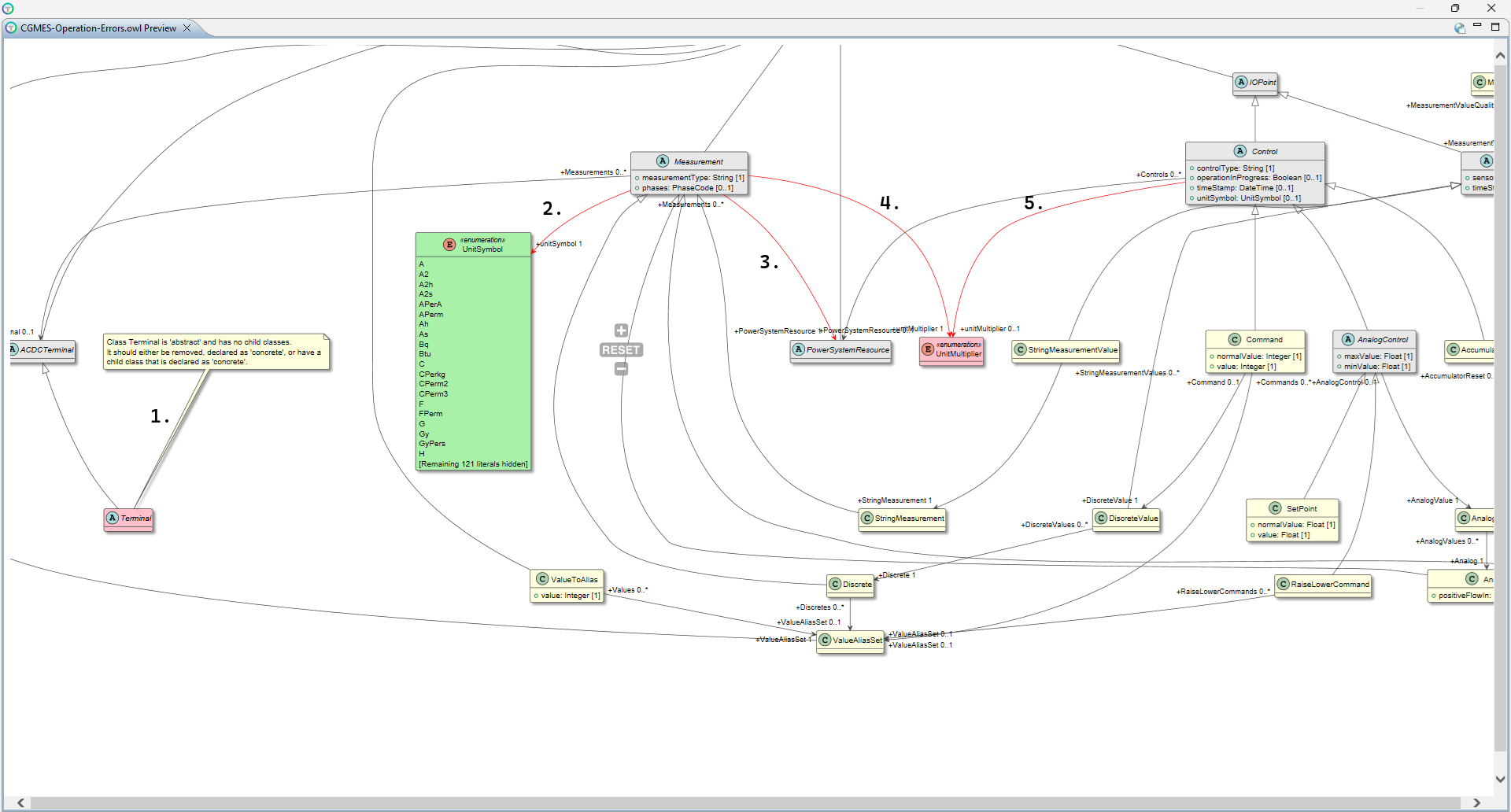
Click on the image to present a larger view.
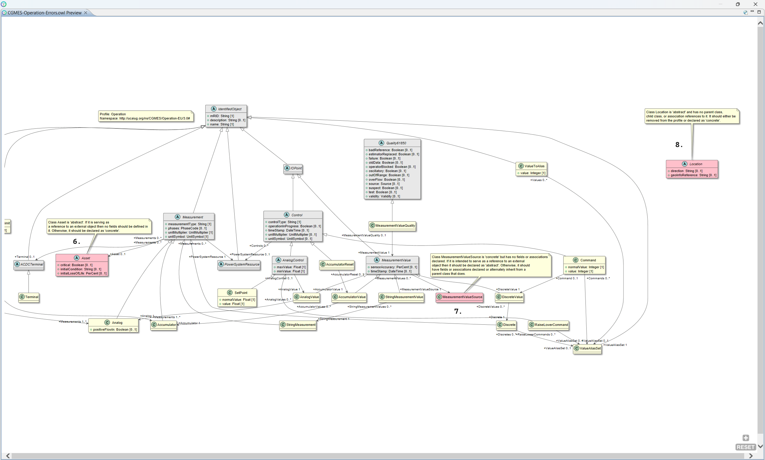
The sections that follow examine each of the above errors in detail, explaining what each one indicates and how to resolve it, beginning with the RDFS diagram style.
RDFS Profile Definition Style
An RDFS-style profile definition targets RDF Schema artifact generation
conforming to IEC 61970-501:2016, Energy management system application
program interface (EMS-API) – Part 501: Common Information Model Resource
Description Framework (CIM RDF) schema. When the diagram style is set to
puml-rdfs-t2b or puml-rdfs-l2r, the Profile Real-Time Preview renders a PlantUML
class diagram that reflects the structural conventions of an RDFS profile
definition. Errors specific to those conventions are visualized directly within
the diagram.
The numbered errors shown in the overview screenshots above are each examined below in sequence, using a deliberately constructed profile that contains each type of error so they can be illustrated and resolved one by one.
Issue 1: Abstract Class with No Concrete Child Classes
What the diagram shows
When a class included in the profile is marked as abstract but has no child classes in the profile that are declared as concrete, the Real-Time Preview flags it with two distinct visual cues:
- The class is rendered in pink/red rather than the standard yellow used for concrete classes. This color convention is used throughout the RDFS diagram style to indicate an abstract class that violates the profile definition rules.
- A note callout is attached directly to the class in the diagram, stating
the problem in plain language. In the example above, the note on
Terminalreads: "Class Terminal is 'abstract' and has no child classes. It should either be removed, declared as 'concrete', or have a child class that is declared as 'concrete'."
The note callout is particularly useful in large profiles where it may not be immediately obvious why a class has been flagged, telling you exactly what the problem is and what your options are to resolve it, without requiring you to inspect the profile definition manually.
What it means
An abstract class in an RDFS profile definition exists to be specialized, and it is expected to have at least one concrete subclass through which instances are actually typed. A profile that includes an abstract class with no concrete child classes creates an ambiguity in the generated RDFS artifact: the class is present but can never be instantiated. CIMTool flags this as a definition error because the resulting artifact would be structurally incomplete.
How to resolve it
There are three ways to address this error, as the note callout itself states:
- Declare the class as concrete. If the class is appropriate to include directly in the profile without requiring a subclass, check the "Make this class concrete" checkbox on the class's Restriction tab in the profile editor.
- Add a concrete subclass. If a suitable subclass exists in the CIM model, add it to the profile and declare it as concrete. This is the preferred resolution when the intent is to preserve the abstract nature of the parent class.
- Remove the class from the profile. If the class is not needed, remove it from the profile entirely via the "Add/Remove" tab.
In the example shown here, Terminal has no subclasses in the CIM model, so
option 2 is not available. The fix applied in the animated GIF below is
option 1, navigating to Terminal via the profile editor's Restriction
tab and checking "Make this class concrete".
Click on the image to present a larger view.
Result
After saving the profile the diagram refreshes automatically. Navigating to
Terminal in the updated diagram confirms the error has been resolved. The
note callout is no longer present and Terminal now appears rendered in the
standard yellow convention for concrete classes.
Issue 2: Attribute Type Not Selected in the Profile Definition
What the diagram shows
When an attribute has been added to the profile but its associated enumeration
or compound type has not been included in the attribute's definition, the
Profile Real-Time Preview flags it with a red association drawn from the class
that owns the attribute to the enumeration or compound type class. In this
example, the unitSymbol attribute on Measurement has been added to the
profile, but the UnitSymbol enumeration that is its declared type has not
been selected as part of the attribute definition. The result is a red
association from Measurement to the UnitSymbol class.
What it means
In the CIM, enumeration and compound types never participate in associations, and are only ever used as the declared type of an attribute. When CIMTool renders a red association between a class and an enumeration or compound type, it is signalling that the attribute exists in the profile but its type has not been properly included in the attribute's definition. The diagram is making visible what would otherwise be an invisible gap in the profile definition: the attribute is present but incomplete.
How to resolve it
The fix is to drill into the attribute definition via the "Add/Remove" tab and select the enumeration or compound type on the attribute's detail page:
- On the "Add/Remove" tab, double-click the class that owns the attribute
(in this example,
Measurement) to drill into its member list. - In the member list, locate the affected attribute (
unitSymbol 1..1) and double-click it to open its attribute detail page. - The attribute detail page shows two columns. The declared type
(
Enumeration: UnitSymbol) will appear in the right-hand (available) column. Move it to the left-hand (selected) column to include it in the attribute's definition. - Save the profile.
Click on the image to present a larger view.
Result
After saving the profile the diagram refreshes automatically. The red
association from Measurement to UnitSymbol is gone. The unitSymbol
attribute now appears correctly as a typed property within the Measurement
class, rendered as unitSymbol: UnitSymbol [1], which is the expected
representation for a properly defined attribute whose type is an enumeration.
Issue 3: Association Target End Not Included in the Profile Definition
What the diagram shows
When an association between two classes has been added to the profile but the
target end of the association has not been included in the profile definition
for that relationship, the Profile Real-Time Preview renders the association in
red between the two classes. In this example, a red association runs from
Measurement to PowerSystemResource.
Note that this error looks visually similar to Issue 2, but its cause is
fundamentally different. In Issue 2 the red arc indicated a missing declared
type on an attribute. Here, it is representing the association between
two classes, Measurement and PowerSystemResource, and that the PowerSystemResource
class is already included in the profile, as confirmed by its presence in the
Outline panel's alphabetical list of currently profiled classes. Because
PowerSystemResource is profiled, it appears in the diagram in grey, the
convention used for abstract classes, rather than pink/red, which would
indicate a class that is entirely absent from the profile. The issue is not
that the class is missing; it is that the association's target end has not
been included in the profile definition for that relationship.
What it means
In a CIM profile definition, adding an association to the profile is not sufficient on its own, since the target end of the association must also be explicitly included in the association's definition within the profile. Until that step is completed, CIMTool cannot fully resolve the relationship and renders the association in red to make the incomplete definition visible.
How to resolve it
The fix follows the same drill-down pattern as Issue 2, but the detail page being completed is an association definition rather than an attribute type selection:
- On the "Add/Remove" tab, double-click the class that owns the
association (in this example,
Measurement) to drill into its member list. - In the member list, locate the affected association (
PowerSystemResource
   1..1
) and double-click it to open its association detail page. - The association detail page shows two columns.
Class: PowerSystemResourcewill appear in the right-hand (available) column. Move it to the left-hand (selected) column to include it in the association's definition. - Save the profile.
Click on the image to present a larger view.
Result
After saving the profile the diagram refreshes automatically. The red association from
Measurement to PowerSystemResource is replaced by a grey association,
confirming that the association is now fully and correctly defined within the
profile, with PowerSystemResource participating as a properly profiled
abstract class on the target end of the relationship.
Issues 4 & 5: Enumeration Type Not Yet Referenced by Any Attribute in the Profile
What the diagram shows
The Profile Real-Time Preview renders UnitMultiplier as an entirely pink/red
class with red arcs running from both Measurement and Control to it.
This is an important distinction from Issue 2, where UnitSymbol appeared
rendered in the default green typical for enumerations. In Issue 2 the
green body indicated that UnitSymbol was already a defined member in the
profile. The pink/red association signalled only that a specific attribute
definition was incomplete.
Here, in Issue 4 and 5, UnitMultiplier is entirely pink/red because it is
not yet a defined member of the profile; CIMTool renders it this way to signal
that the enumeration is wholly unresolved within the profile.
What it means
Both Measurement and Control have a unitMultiplier attribute in the CIM
whose declared type is the UnitMultiplier enumeration. Both attributes have
been added to the profile, but neither has had UnitMultiplier selected in the
attribute's definition on the "Add/Remove" tab. Until at least one of them
does so, UnitMultiplier remains entirely unresolved and is rendered fully
pink/red. The two red arcs, one from Measurement and one from Control,
each represent the same underlying problem on their respective attribute
definitions.
How to resolve it
Each attribute definition must be completed independently, following the same
drill-down pattern as Issue 2. Issue 4 addresses Measurement's
unitMultiplier attribute first; Issue 5 then addresses Control's.
Issue 4: Measurement → unitMultiplier:
- On the "Add/Remove" tab, double-click
Measurementto drill into its member list. - Double-click
unitMultiplier 1..1to open its attribute detail page. Enumeration: UnitMultiplierwill appear in the right-hand (available) column. Move it to the left-hand (selected) column.- Save the profile.
After saving, the diagram refreshes. The red arc from Measurement to
UnitMultiplier disappears and unitMultiplier: UnitMultiplier [1] now
appears as a correctly typed property within the Measurement class.
Critically, UnitMultiplier itself is now rendered in green, because
its membership in the profile has been established through Measurement's
attribute definition. The red arc from Control remains, but UnitMultiplier
is no longer entirely unresolved.
Issue 5: Control → unitMultiplier:
- Double-click
Controlon the "Add/Remove" tab to drill into its member list. - Double-click
unitMultiplier 0..1to open its attribute detail page. Enumeration: UnitMultiplierwill appear in the right-hand (available) column. Move it to the left-hand (selected) column.- Save the profile.
Click on the image to present a larger view.
Result
After the second save the diagram refreshes fully. Both red arcs are gone.
UnitMultiplier no longer appears as a standalone class in the diagram,
and is now correctly resolved as the declared type of the unitMultiplier
attribute on both Measurement and Control, appearing as a typed property
within each class respectively.
Issue 6: Abstract Class with Fields Defined
What the diagram shows
The Profile Real-Time Preview renders Asset in pink/red with a note callout
attached, reading: "Class Asset is 'abstract'. If it is serving as a reference
to an external object then no fields should be defined in it. Otherwise, it
should be declared as 'concrete'."
Unlike Issue 1 where the class was abstract simply because it lacked a concrete
child, here Asset is abstract and has fields defined on it (critical,
initialCondition, initialLossOfLife). This combination is flagged because
it does not fit either of the two valid patterns for an abstract class in an
RDFS profile definition.
What it means
In an RDFS profile definition, an abstract class can serve one of two valid roles:
- An external reference: the class is included in the profile not because instances of it will be fully described within the data exchange, but because other classes need to reference instances of it that exist outside the scope of the exchange. The class acts as a typed pointer to an external resource. For this role, the class should have no fields defined, since fields would never be populated in practice and their presence is misleading.
- A parent class to be specialized: the class exists to be subclassed by one or more concrete child classes that inherit its structure. For this role, having fields is appropriate, but the class itself must not be directly instantiable and must remain abstract.
Asset is currently abstract with fields defined, so it cannot serve as a clean
external reference (because it has fields) and it cannot serve as a parent class
to be specialized (because it has no concrete child classes in the profile).
CIMTool flags this as a definition error because the intent is ambiguous and
must be resolved explicitly.
How to resolve it
There are two valid resolutions, depending on the intended role of Asset in
the profile:
- If
Assetis intended as an external reference: remove the fields from its profile definition via the "Add/Remove" tab. Navigate toAssetin the member list, select all three fields (critical,initialCondition,initialLossOfLife) in the selected column and remove them.Assetwill then be a clean abstract class with no fields, appropriate for use as an external reference pointer. - If
Assetis intended to carry data: declare it concrete via the Restriction tab by checking "Make this class concrete".
In the example shown here, the fix applied is option 1, removing the three
fields from Asset's profile definition, leaving it as a clean abstract class
suited to its role as an external reference.
Click on the image to present a larger view.
Result
After saving the profile the diagram refreshes automatically. Asset now
renders in grey, the convention for abstract classes, with no fields
and no note callout. Its role as an external reference is now correctly
expressed in the profile definition.
Issue 7: Concrete Class with No Fields or Associations
What the diagram shows
The Profile Real-Time Preview renders MeasurementValueSource in pink/red with a
note callout reading: "Class MeasurementValueSource is 'concrete' but has no
fields or associations declared. If it is intended to serve as a reference to
an external object then it should be declared as 'abstract'. Otherwise, it
should have fields or associations declared or alternately inherit from a parent
class that does."
This is in some ways the mirror image of Issue 6. Where Issue 6 showed an abstract class that had fields it should not have, Issue 7 shows a concrete class that has no fields or associations, and no parent class from which to inherit them.
What it means
A concrete class in an RDFS profile definition is expected to carry substance: either its own fields or associations, or those inherited from a parent class. A concrete class with none of these has no meaningful content to contribute to a data exchange. As noted in Issue 6, a class that is intended purely as an external reference (a typed pointer to an object existing outside the scope of the exchange) should have no fields, but for that role, abstract is the correct declaration, not concrete.
CIMTool flags MeasurementValueSource because it is concrete, has no
fields or associations, and has no parent class from which to inherit them.
The note callout presents two paths to resolution: declare it abstract (if it
is serving as an external reference) or give it fields, associations, or a
parent class (if it is meant to carry data).
How to resolve it
There are three valid resolutions, as the note callout itself states:
- Declare the class as abstract. If
MeasurementValueSourceis intended purely as an external reference (a typed pointer to an object existing outside the scope of the exchange), uncheck the "Make this class concrete" checkbox on the Restriction tab. A clean abstract class with no fields is the correct expression of that role. - Add a parent class. Navigate to
MeasurementValueSourceon the Restriction tab and select a super class. This allows the class to remain concrete while inheriting fields from a parent, satisfying the requirement that a concrete class must carry substance. In the example shown here, this is the fix applied, withIdentifiedObjectselected as the super class, providing inherited fields without requiring any direct field definitions onMeasurementValueSourceitself. - Add fields or associations directly. Navigate to
MeasurementValueSourceon the "Add/Remove" tab and add one or more fields or associations to its profile definition.
Click on the image to present a larger view.
Result
After saving the profile the diagram refreshes automatically.
MeasurementValueSource now renders as a yellow concrete class with no
note callout. The pink/red coloring is gone and the error is resolved. By
inheriting from IdentifiedObject, it now has a parent class that provides
the substance required of a concrete class in an RDFS profile definition.
Issue 8: Isolated Abstract Class with No Parent, Child, or Associations
What the diagram shows
The Profile Real-Time Preview renders Location in pink/red with a note callout
reading: "Class Location is 'abstract' and has no parent class, child class,
or association references to it. It should either be removed from the profile
or declared as 'concrete'."
Location has two fields defined (direction: String [0..1] and
geoInfoReference: String [0..1]) but is declared abstract, and has no
parent class, no concrete child classes, and no association references
connecting it to any other class in the profile.
What it means
An abstract class exists to be specialized or referenced through its relationships. If a class has no parent to inherit from, no child classes to specialize it, and no associations connecting it to anything else in the profile, it is completely isolated, with no path through which it could ever be instantiated or referenced in a data exchange. In this state, the class serves no purpose in the profile regardless of what fields it carries.
Declaring it concrete resolves this because it changes the class's role
entirely: instead of requiring specialization or indirect reference, it becomes
directly instantiable. Instances of a concrete class can be included in a data
exchange as standalone objects, a legitimate and meaningful role even without
parent, child, or association relationships. The presence of fields
(direction and geoInfoReference) confirms that Location is intended to
carry data, making concrete the appropriate declaration.
How to resolve it
There are two valid resolutions, as the note callout itself states:
- Declare the class as concrete. Navigate to
Locationon the Restriction tab and check the "Make this class concrete" checkbox. SinceLocationalready has fields defined (directionandgeoInfoReference), declaring it concrete is sufficient, and it gains a legitimate role as a directly instantiable class whose instances can participate in a data exchange. No further changes to the profile definition are needed. This is the fix applied in the example shown here. - Remove the class from the profile. If
Locationis not needed, remove it from the profile entirely via the "Add/Remove" tab.
Click on the image to present a larger view.
Result
After saving the profile the diagram refreshes automatically. Location now
renders as a yellow concrete class with its two fields displayed and no
note callout. It is now correctly defined as a directly instantiable class
whose instances can participate in a data exchange.